- My Roles: Writer, SME, Graphic Designer, 3D Artist
- Tools: PowerPoint, Nimbus Capture, Gimp, Blender, FreeCAD
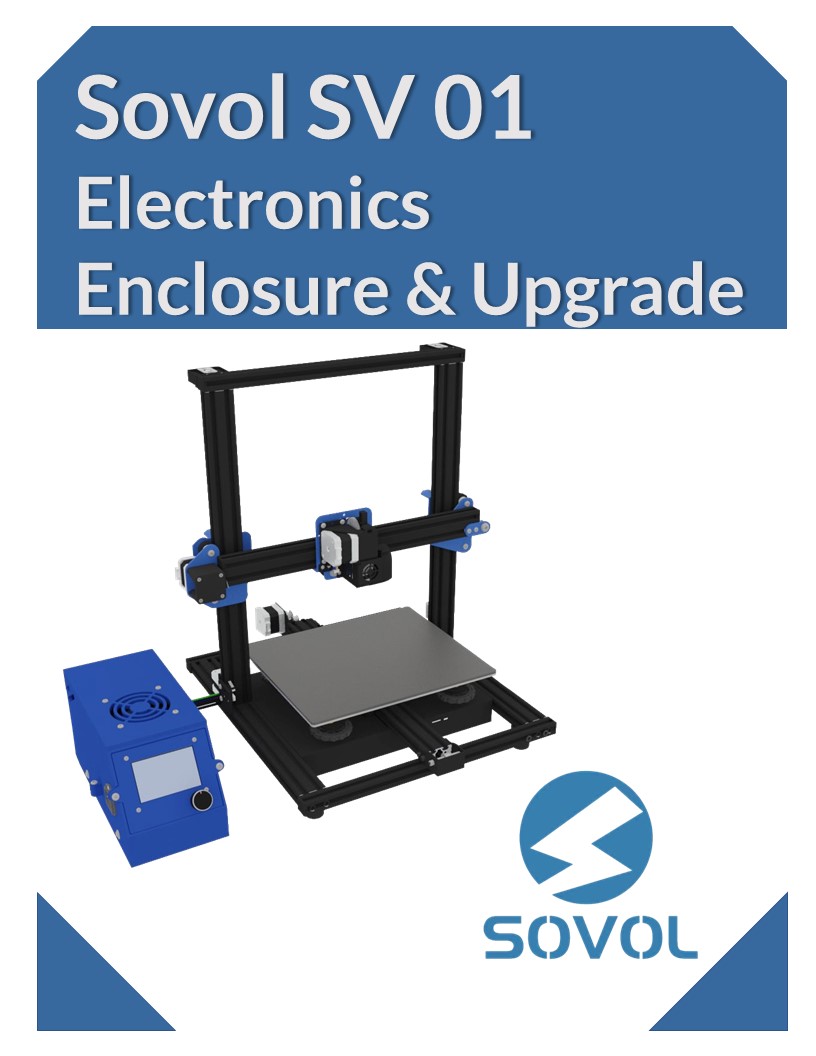
Assembly manuals are important documents for both industrial and commercial applications. A well-designed assembly manual allows for products to be assembled faster and for the user to quickly gain confidence in the work they are doing. This manual walks users through assembling an upgraded electronics enclosure for the Sovol SV 01 3D printer.
One of my reasons for creating this document was to show how 3D models can be used to prepare clean, professional graphics to illustrate steps of an assembly process. Truthfully, it would be much easier to perform this assembly in real life and simply take photographs of each step. Photographs, however, can often look amateurish in documents like this and don't allow for the level of control that 3D renderings can offer. Working in a 3D space, the graphic designer can carefully position objects, lights, and cameras anywhere and make fine adjustments to the settings of them. If this were a more complex product, say components of a jet engine, creating graphics from 3d models would also more practical and take less time.
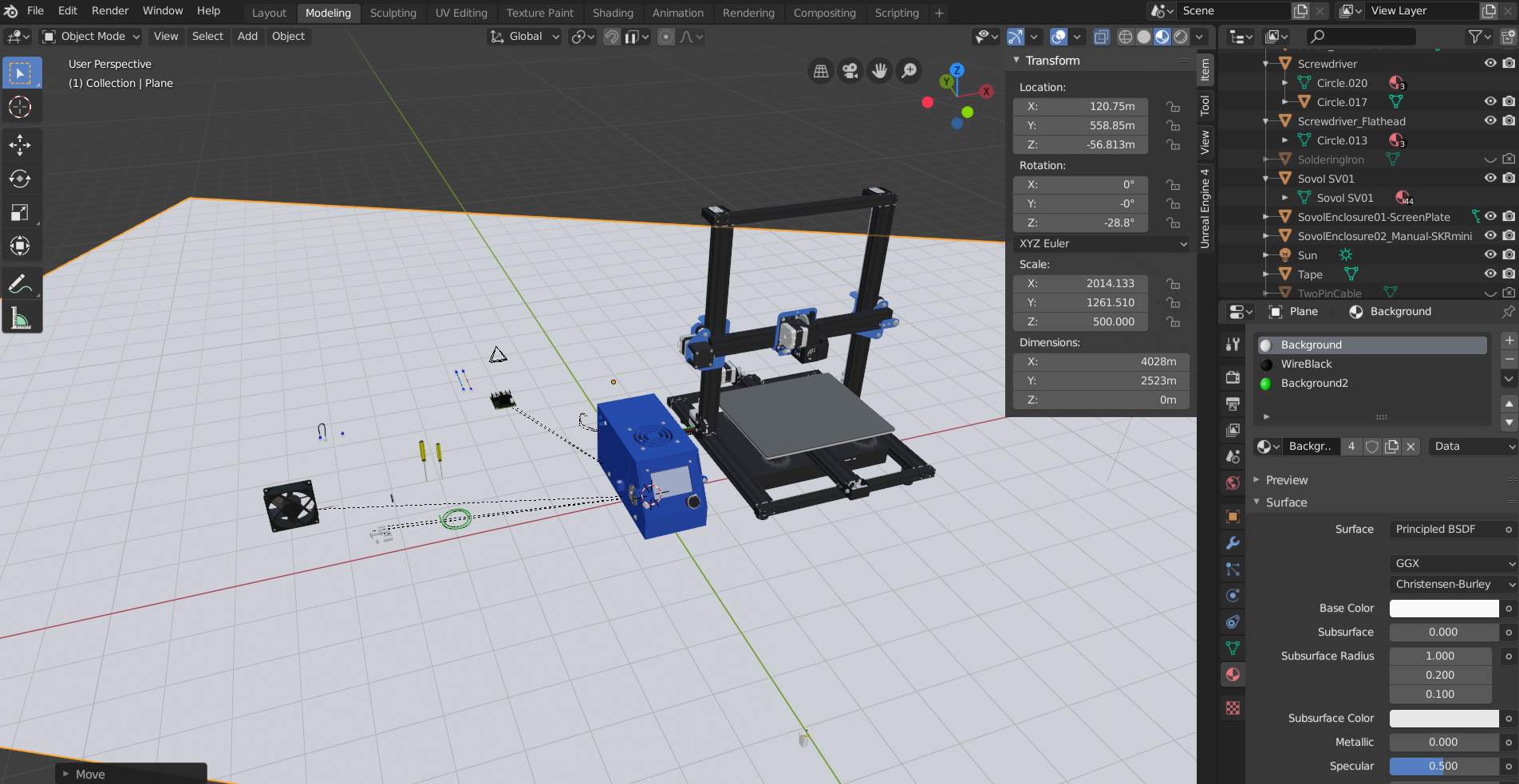
To create the 3D graphics, I used a combination of several programs. The model of the actual 3D printer was an existing model, but the other components were designed using FreeCAD. FreeCAD is an open-source CAD suite that allows for extremely precise designing of parts and models. I then imported all of the models into Blender where I textured the surfaces of each component and "assembled" them virtually. Blender also includes a 3D camera to render still images from the virtual scene. I went through the assembly process with the 3D models and rendered many still images along the way. Lastly, I used Gimp (an open-source alternative to Photoshop) to edit the images by removing backgrounds, cropping objects, and adding arrows and other "highlighting" elements. With the graphics prepared, I used PowerPoint to build the layout, add alternate text to the images, and export the final PDF.
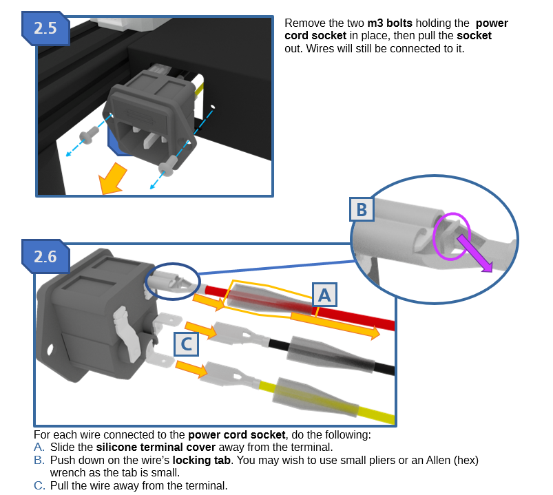
Another goal of mine was to present the assembly steps in such a way that text instructions wouldn't necessarily be needed. Arrows in different colors clearly show where bolts should be added and removed, and adding "letter labels" on some of the graphics helps the reader visualize the order that small tasks need to be done in. I still included text summaries with each step to add an extra modality for conveying the information, but someone who skips the text should still be able to follow along with little trouble.
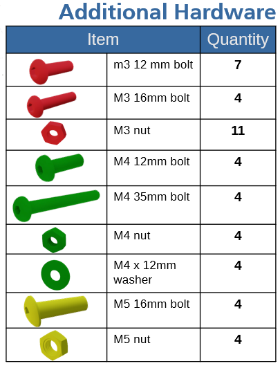
I took care to make sure that this document included all of the sections that would be helpful to someone completing this assembly project. The document includes safety information, materials list, troubleshooting section, and references of wiring diagrams and technical drawings (which I also prepared using FreeCAD). The overall design of the document is meant to feel clean and professional by maintaining consistent styling with colors, fonts, and arrangement. This consistency helps make the document pleasing to look at and easy to follow.